Ramiz Arshad Khan

 Neurosky Headset:


MPU-6050:

It is the world first integrated motion tracking device which notes 6-axis motion. It has 3 axis gyroscope and 3 axis accelerometer and a DMP that is Digital Motion Processor. It’s all in small 4x4x0.9mm package. I2C bus is used as a standard bus for data transmission.

There are many breakout boards which contain MPU-6050 chip but we have GY-521.

About I2C:

This I2C bus is used by MPU6050 for communication with Arduino. The physical 12C bus has two wires that is SDA and SCL. SCL is clock line which is used to synchronize all the transferred data. SDA is the data line. These both lines are open drain drivers. And can be driven low. To make it go high just provide a pull up resistor to 5V.

These devices on I2C are masters or slaves. Master starts the clock and starts the data transfer. There are multiple slaves on this bus but it contains only one master. These both master and slave can be used for data transfer but this all transfer is only controlled by master. During the transfer of data SDA should not be changed while SCL is high. All data is transferred only in 8 bits. MSB is first.

The SCL speed is about 100 KHz.


GY-521:

This board contains a 3 axis gyroscope and a 3 axis accelerometer in a MPU-6050 chip.  These are referred as an IMU that is Inertial Measurement Unit. DOF is Degree of Freedom and is referred as number of sensor inputs, so the chip with 3 axis gyroscope and 3 axis accelerometers is a 6-DOF IMU.

It contains a voltage regulator in the chip so we can apply 3.3V or 5V from arduino board. We put voltage as said above from the arduino board to GY-521 board. GND of GY-521 is connected to ground pin in arduino board. SDA pin is of data and SCL is clock. We connect A4 of arduino with SDA and A5 of arduino with SCL.


C:\Users\Haseeb\Desktop\Untitledg.png

Figure3.12: Front View

C:\Users\Haseeb\Desktop\da.png

Figure3.13: Back view


  1. Purpose of every pin:

  • VCC:

It is pin from where we give power to the chip.

  • GND:

It is ground.

  • SCL:

It is Clock.

  • SDA:

It is for data.

  • XCL:

  • XDA:

  • ADO:


  • INT:

It is pin for interrupt.


  1. Accelerometers:

A device which used for measurement and acceleration of a moving body are vibrating body. Orientation computed from an accelerometer depends on a constant gravitational pull of 1g that is 9.8m/s^2 down in direction.

If there is no other force acting on it then the magnitude is 1g and the rotation of sensor can be computed with the position of vector of acceleration. Digital accelerometers use serial protocol like I2C, SPI or USART for giving information. Analog accelerometersgive output voltage in predefined ranges. Figure 3.14C:\Users\Haseeb\Desktop\vhv.png


  1. Gyroscope:

It is an instrument which measures angular velocity and not angular orientation.


Accelerometer Range:

It ranges in ±2, ±4, ±8, ±16g.

Gyroscope ranges: 

It ranges in ± 250, 500, 1000, 2000 °per second.

Voltage range:

It ranges from 3.3V - 5V.


  Bluetooth

Introduction & History:

Bluetooth is a device which exchange data over short distance from fixed and mobile. It uses Ultra high frequency radio waves in the ISM band from 2.4 to 2.485 GHz. It is basically used in mobile devices, laptops, tabs, portable devices etc. It built personal area networks (Pans). It can connect several devices to overcome problem of synchronization. It is invented in 2004 by Ericsson. Bluetooth is managed by Bluetooth Special Interest Group Bluetooth is now used in different devices made by different organizations. These organizations must be either promoter member or associate with Bluetooth SIG before they access Bluetooth specifications. The SIG owns Bluetooth word mark, figure mark and combination mark. These trademarks are licensed out for use to Companies that are incorporating Bluetooth wireless technology into their products. The main tasks for the SIG are to publish the Bluetooth specifications, protect the Bluetooth trademarks and evangelize Bluetooth wireless technology.

Implementation:

Bluetooth operates at frequencies between 2.4 and 2.485 GHz including guard bands of 2 MHz at the bottom end and 3.5 MHz at the top. This is globally unlicensed Industrial Scientific and Medical 2.4 GHz short-range radio frequency band. Bluetooth uses a radio technology called frequency hopping spread spectrum. Bluetooth divides transmitted data into packets, and transmits each packet on one of 79 designated Bluetooth channels. Each channel has a bandwidth of 1 MHz Bluetooth 4.0 uses 2 MHz spacing, which accommodate 40 channels. The first channel starts at 2402 MHz and continues up to 2480 MHz in 1 MHz steps. It usually performs 1600 hops per second, with Adaptive Frequency-Hopping enabled. Originally, Gaussian frequency-shift keying modulation was the only modulation scheme available. Since the introduction of Bluetooth 2.0+EDR, π/4-DQPSK and 8DPSK modulation may also be used between compatible devices. Devices functioning with GFSK are said to be operating in basic rate mode where an instantaneous data rate of 1 Mbit/s is possible. The term Enhanced Data Rate is used to explain π/4-DPSK and 8DPSK schemes, each giving 2 and 3 Mbit/s respectively. The grouping of these modes in Bluetooth radio technology is classified as a "BR/EDR radio".


Applications:

Wireless controlled of and communication among a mobile phone and a hands free headset. This was one of the earliest applications to become popular. Wireless controlled of and communication between a mobile phone and a Bluetooth compatible car stereo system. Wireless controlled of and communication with tablets and speakers such as IOS and Android devices. Wireless Bluetooth head set and Intercom. A headset is occasionally called "a Bluetooth". Wireless stream of audio to head phones with or without communication capabilities. Wireless networking between PCs in a confined space and where little bandwidth is required.


HC-06 Bluetooth Module:

HC serial Bluetooth products consist of Bluetooth serial interface module and Bluetooth adapter. Bluetooth serial module is used for converting serial port to Bluetooth. These modules have two modes: master and slaver device. The device named after even number is defined to be master or slaver when out of factory and can’t be changed to the other mode. But for the device named after odd number, users can set the work mode (master or slaver) of the device by AT commands.


  1. Technical data:

•Chipset: CSR 

•Bluetooth V2.0 

•Working voltage: 3.3V 

•Current: pairing 20~30mA, connected 8mA 

•Dimensions: 1.06 in x 0.51 in x 0.04 in 

•Dimensions: 2.7 cm x 1.3 cm x 0.1 cm 

• Default baud rate: 9600

•Weight: 0.18 oz (5 g)

D:\hc06.JPG Figure 3.11


  How To Use Servo Motors:

Servo motors have characteristics just like other types of motors that are operating speed, current, voltage, torque, resolution and pulse, control pulse and weight.


  • Current and Voltage:

The current and the power supply voltage are specified for each servo motor. It depends on the application that for what purpose it is going to be used. Common servo motors works with power supply voltage of 4 to 6V and has current 100mA to 2A.

  • Operating Speed:

It is defined as time which is required for shaft to reach till it reaches a specified position. Common servo motors have 0.05 to 0.2s seconds per 60 degree.

  • Torque:

It is from 0,5 to 10Kg per cm.

  • Control Pulse:

It is a pulse which is used to position shaft. There are two important types of control pulses. One is with center position in 1 to 2 ms and other is 1.25 to 1.75.

  • Resolution:

It is precision by which shaft is positioned whenever it receives external signal. It is from 1 degree to 10 degree.

  • Size and weight:

It is important aspect. It has weight from 15 to 200g.

Advantages of Servo Motors:

  • If load is placed on motor, current is increased by the driver and this current to motor coil attempts to rotate motor. No out of step condition.

  • Possibility of high speed operation is possible.

Disadvantages of Servo motors:

It is when stop, its rotor continues to move back and forth, so that is is not suitable.

Applications of Servo Motors:

  • It is used in machine tools, material handling, assembly lines, robotics, and CNC machinery or automated manufacturing.

  • It is used in airplanes.

  • It is used to control the position and movement of elevators.

  • It is used in robots just because of their smooth switching on and off and the accurate positioning.

  • They are widely used in aerospace to maintain hydraulic fluid in the hydraulic systems.

  • It is used in radio controlled toys.

  • Most electronic devices like DVDs etc use this to replay or extend disc trays.

  • It is used in automobiles to maintain speed of vehicles.

 Technology and Tools

There is a list of components which we will be using in Brain controlled robotic project depending upon its mechanical structure and electronic way of operating it using different technologies. 

The task which we are performing in our project can be performed through many different ways but we have selected and used the specific design and components depending upon the following factors.

  • Cost efficient

  • Availability

  • User friendly

As discuss in the first chapter of “beginning” we will be using following components in our project 

  • Arduino Board (Mega 2560)

  •  Robotic arm having Servo motors

  • Bluetooth ()

  • Neurosky Headset


Arduino:

Is an open source platform which can sense and control more of the physical world based on a simple microcontroller board. Arduino can be used to develop interactive objects, taking inputs from a variety of switches or sensors and controlling a variety of objects e.g. lights, motors and other physical outputs.

The Arduino programming language is an implementation of wiring, a similar physical computing platform, which is based on the processing multimedia programming environment.

There are many other microcontrollers available in market for physical computing Net media’s BX-24, phidgets, MIT’s handy board etc and many others offer similar functionality. Arduino also simplifies the process of working with microcontrollers, but it offers some advantages for teachers and students over other systems.

Arduino board is relatively inexpensive compared to other microcontroller platforms.

The arduino programming environment is easy to use for beginners yet flexible enough for advanced users to take advantage of as well.

The arduino software is published as open source tools available for extension by experienced programmer’s .The language can be expanded through C++ libraries.

Arduino Mega 2560:


  1. Pins configuration:

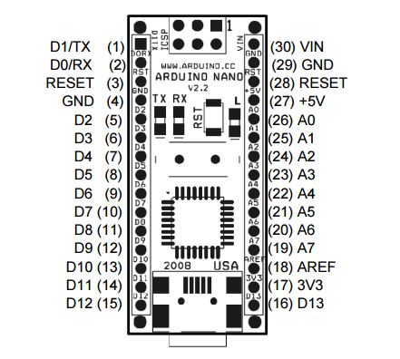
           UntitledFigure 3.2

D0-D13:

The pins 1-2 and 5-16 are named as D0-D13 are I/O digital input/output from port 0 to 13.

Reset:

The pins 3 and 28 are inputs and performs the operations of reset.

Ground:

The 4 and 29 PWR pins which performs the operation of supply ground.

3V3:

It is an output which gives the +3.3v.

AREF:

Pin 18 named as AREF is the input pin which is the ADC refrence.

A7-A0:

The pins 19-26 named as A7-A0 are the analog input channel from 0 to 7.

+5V:

Pin 27 is the input or output which gives +5v output from on board regulator or +5v input from external power supply.

Vin:

The pin no 30 is the input supply voltage.

3.1.2 Arduino Mega:

Untitled123(Front view Figure 3.3)

Untitled1234(Back view Figure 3.4)

The arduino Uno is a microcontroller board based on the Atmega328.It has 14 digital input/output pins which 6 can be used as PWM outputs,6 analog inputs, a 16 MHz ceramic resonator, a USB connection ,a power jack an ICSP header and a reset button. It contains everything needed to support the microcontroller simply connect it to a computer with a USB cable or power it with a AC to DC adapter or battery to get start.


  1. Pins configuration:


CN-arduino-uno-fig1-enlarge Figure 3.5


Serial:

Pin 0 and 1used to receive (RX) and transmit (TX) TTL serial data.

External Interrupts:

Pins 2 and 3 can be configured to trigger an interrupt on a low value a rising or falling edge or a change in value.


PWM:

Pins 3, 5, 6, 9, 10 and 11 provide 8-bit PWM output with the analog write () function.

SPI:

SPI 10 (SS), 11(MOSI), 12(MISO),13(SCK) these pins support SPI communication using the SPI library.

LED:

There is a built in LED light at pin 13 when the pin has high value the light is on and when the pin has low value it would be off.

A0-A5:

The arduino Uno has 6 analog inputs named as A0 to A5 each of which provides 10 bits of resolution e.g.1024 different values.

TWI:

A4 or SDA pin and A5 or SCL pin performs TWI communication using wire library.

AREF:

This pin is the reference voltage for the analog inputs.

Reset:

Bring this line low to reset the arduino. Typically it is used to add a reset button to shields which block the one on the board.


DC Motors:

DC motor is a type of motor which converts direct current electrical power into mechanical power. There are many types of DC motors. One which we are using in our robotic arm is servo motor.
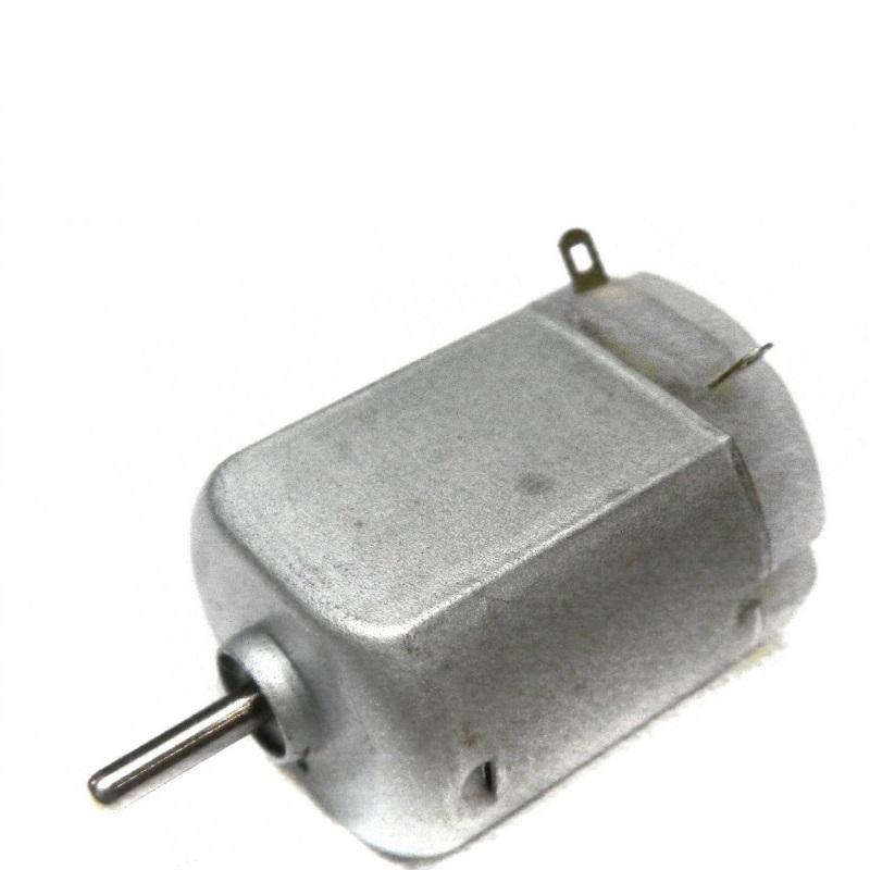
MM10 DC motor

Figure 3.6 : Simple DC motor


Servo motors: 

These are mechanical devices which are used to move output shaft, which is attached to servo wheel or arm. These are mostly used for position, velocity and torque control. Usually the shaft can move up to 180 degrees of angle.

Untitledmm

Figure 3.7

A main part of servo motor is a DC motor inside it. It also contains a potentiometer which is known as position sensor, a gear system and control electronics.

Control circuit has electronic components generally having an oscillator and controller which receives signal from sensor and signal activates the direction of the motor necessary to the position shaft in required position.

Untitlednn

Figure 3.8


 It has 3 wires. One is for power, one is for ground and one is for PWM. By sending a coded signal, we can have any position of the shaft of servo motor. It can be positioned to specific angular positions and it will remain at that position until the coded signal exists. By changing the code, we can change angular position of shaft.

Servos which we are using have 13KG/cm operating torque. It works at 100mA current. Voltage used can be from 3 to 7.2V. Operating speed is 0.17 seconds per 60 degrees at 4.8V and 0.13 seconds per 60 degrees at 6V.

Untitledkk

Figure 3.9: External View of Servo motor

Micro servo motor:

Micro Servo motor is used in the wrist. Its weight is 9g. Operating torque is 1.6KG/cm. It has plastic gear. It uses 3.5 to 6V.

Untitledmmn

Figure 3.10: Micro Servo motor

How does a servo motor work?

DC motor moves the gear system with large reduction ratio. The shaft imposes force on load and acts on the axis of a feedback potentiometer. Potentiometer senses position of axis and sends corresponding voltage to operational amplifier. Voltage compared to input voltage determines the desired position of a shaft producing voltage in output of comparator. Voltage powers motor such that a shaft moves in important direction to align with angle that is equal to the voltage applied to input.


Why we use servo motors:

We use it because it gives best accurate results.